4.- Procedure:
4.1. Study the attached schematic.
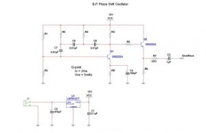
• Capacitor values are given and are included in the kit provided.
• Assume that the BJTs have a beta of 100.
4.2. Design the network with a Q1 Ic of 2 mA, and a VCE of 5 volts. Show all equations in your final
report. Choose 5% values and show them in your final schematic and parts list.
4.3. Measure and record the voltages of Q1’s base, emitter and collector. Compare them to the
calculated values. (Note: You may want to adjust R1 to get a better sine wave).
4.4. Calculate the output impedance of the network of Q2. Without R7, measure the output
impedance of Q2 and compare it to the calculated value. Connect the speaker to the output.
4.5. Measure and record the voltages of Q2’s base, emitter and collector. Compare them to the
calculated values.
4.6. Chose frequency selective resistors R3 and R4 to give (as close as possible) an output frequency
of 1 kHz. (see research section).